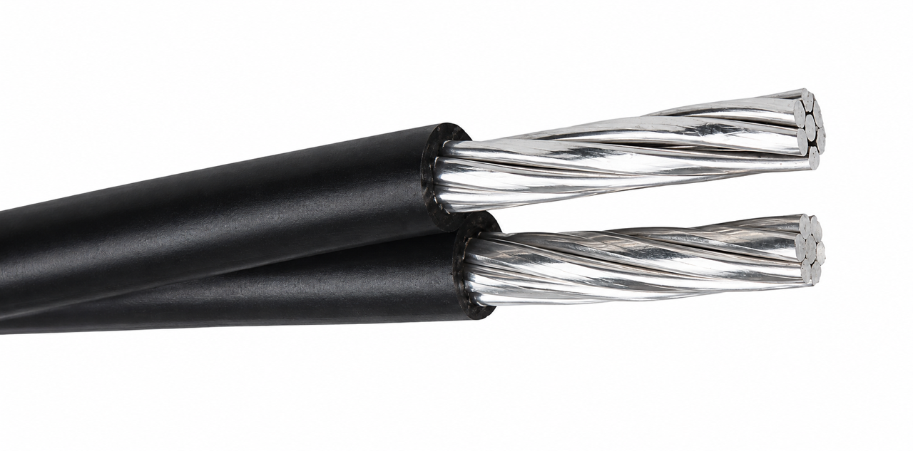
Primarily used for overhead service applications such as street lighting, outdoor lighting, and temporary service for construction.
Primarily used for overhead service applications such as street lighting, outdoor lighting, and temporary service for construction. To be used at voltages of 1000 volts phase - to - phase or less and at conductor temperatures not to exceed 70°C for polyethylene (PE) and Polyvinyl chloride (PVC) insulated conductors or 90°C for cross-linked polyethylene (XLPE) insulated conductors.
GB/T 12527(Equivalent to IEC 60502-1)Aerial Insulated Cables for Rated Voltages up to and Including 1kV
IEC 60228 Conductors of insulated cables
Component | Description from source webpage |
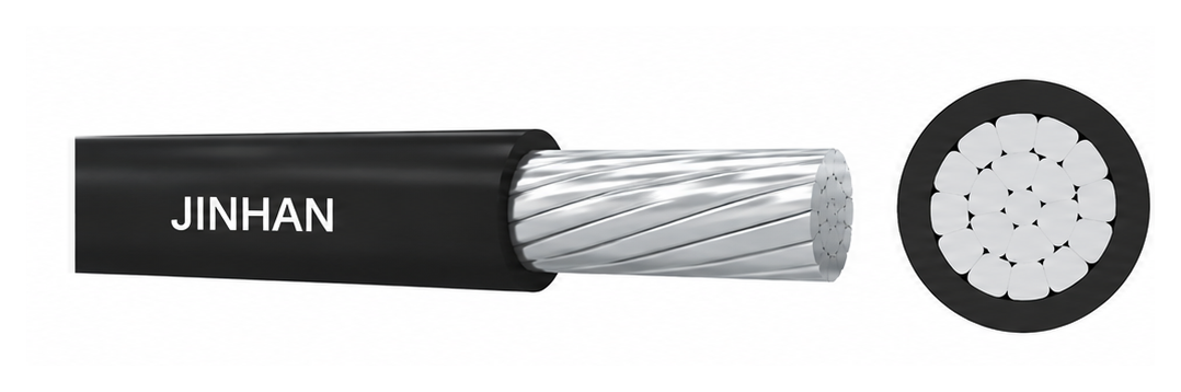
Conductor | Stranded, circular-compacted or uncompacted aluminum, copper, aluminum-alloy, ACSR, etc. |
Insulation | Thermoplastic polyethylene (PE), polyvinyl chloride (PVC), or cross-linked polyethylene (XLPE). |
Colour / weather resistance | Insulation is black and weather- and UV-resistant, as stated on the webpage. |
Auxiliary core (k) | The auxiliary core k is a load-bearing core or a neutral core with a load. Its cross-section is optional to match the main core according to factory requirements. |
Core notation | (A) means steel-carrying stranded wire; (B) means aluminum-alloy-carrying stranded wire. |
Cable type | No. of cores | Nominal cross-sectional area |
CU/PVC, AAC/PVC, AAAC/PVC, CU/PE, AAC/PE, AAAC/PE, CU/XLPE, AAC/XLPE, AAAC/XLPE | 1 | 10–400 mm² |
Same types as above | 2 or 4 | 10–120 mm² |
AAC/PVC, AAC/PE, AAC/XLPE | 3+k* | 10–120 mm² |
Nominal size (mm²) | Min. no. of wires | Approx. conductor diameter (mm) | Nominal insulation thickness (mm) | Max. cable diameter (mm) | Max. DC resistance at 20°C — hard Cu (Ω/km) | Max. DC resistance at 20°C — annealed Cu (Ω/km) | Breaking load — hard Cu (N) |
10 | 6 | 3.8 | 1.0 | 6.5 | 1.906 | 1.83 | 3471 |
16 | 6 | 4.8 | 1.2 | 8.0 | 1.198 | 1.15 | 5486 |
25 | 6 | 6.0 | 1.2 | 9.4 | 0.749 | 0.727 | 8465 |
35 | 6 | 7.0 | 1.4 | 11.0 | 0.540 | 0.524 | 11731 |
50 | 6 | 8.4 | 1.4 | 12.3 | 0.399 | 0.387 | 16052 |
70 | 12 | 10.0 | 1.4 | 14.1 | 0.276 | 0.268 | 23461 |
95 | 15 | 11.6 | 1.6 | 16.5 | 0.199 | 0.193 | 31759 |
120 | 18 | 13.0 | 1.6 | 18.1 | 0.158 | 0.153 | 39911 |
150 | 18 | 14.6 | 1.8 | 20.2 | 0.128 | 0.124 | 49505 |
185 | 30 | 16.2 | 2.0 | 22.5 | 0.1021 | 0.0991 | 61846 |
240 | 34 | 18.4 | 2.2 | 25.6 | 0.0777 | 0.0754 | 79823 |
Nominal size (mm²) | Min. no. of wires | Approx. conductor diameter (mm) | Nominal insulation thickness (mm) | Max. cable diameter (mm) | Max. DC resistance at 20°C — AAC (Ω/km) | Max. DC resistance at 20°C — AAAC (Ω/km) | Breaking load — AAC (N) | Breaking load — AAAC (N) |
10 | 6 | 3.8 | 1.0 | 6.5 | 3.080 | 3.574 | 1650 | 2514 |
16 | 6 | 4.8 | 1.2 | 8.0 | 1.910 | 2.217 | 2517 | 4022 |
25 | 6 | 6.0 | 1.2 | 9.4 | 1.200 | 1.393 | 3762 | 6284 |
35 | 6 | 7.0 | 1.4 | 11.0 | 0.868 | 1.007 | 5177 | 8800 |
50 | 6 | 8.4 | 1.4 | 12.3 | 0.641 | 0.744 | 7011 | 12569 |
70 | 12 | 10.0 | 1.4 | 14.1 | 0.443 | 0.514 | 10354 | 17596 |
95 | 15 | 11.6 | 1.6 | 16.5 | 0.320 | 0.371 | 13727 | 23880 |
120 | 15 | 13.0 | 1.6 | 18.1 | 0.253 | 0.294 | 17339 | 30164 |
150 | 15 | 14.6 | 1.8 | 20.2 | 0.206 | 0.239 | 21033 | 37706 |
185 | 30 | 16.2 | 2.0 | 22.5 | 0.164 | 0.190 | 26732 | 46503 |
240 | 30 | 18.4 | 2.2 | 25.6 | 0.125 | 0.145 | 34679 | 60329 |
300 | 30 | 20.8 | 2.2 | 27.2 | 0.100 | 0.116 | 43349 | 75411 |
400 | 53 | 23.2 | 2.2 | 30.7 | 0.0778 | 0.0904 | 55707 | 100548 |
The webpage also includes the following covered-conductor data tables. They are presented separately because the source lists them as PVC-covered conductors for overhead power lines.
Nominal area (mm²) | Stranding / wire diameter (mm) | Bare conductor diameter (mm) | Max. resistance at 20°C (Ω/km) | Approx. breaking load (kN) | Covered conductor OD — Type 8 (mm) | Covered conductor OD — Type 16 (mm) | Approx. mass — Type 8 (kg/km) | Approx. mass — Type 16 (kg/km) |
14 | 7/1.60 | 4.80 | 1.303 | 5.744 | 6.8 | 8.4 | 160 | 190 |
16 | 3/2.65 | 5.70 | 1.106 | 6.590 | 7.7 | 9.3 | 180 | 220 |
32 | 3/3.75 | 8.06 | 0.5520 | 12.71 | 10.5 | 12.1 | 350 | 390 |
35 | 7/2.50 | 7.50 | 0.5337 | 14.097 | 9.9 | 11.5 | 360 | 400 |
70 | 7/3.55 | 10.65 | 0.2646 | 26.88 | 13.5 | 14.7 | 690 | 750 |
100 | 7/4.30 | 12.90 | 0.1810 | 37.64 | 15.7 | 16.9 | 990 | 1060 |
Nominal area (mm²) | Stranding / wire diameter (mm) | Bare conductor diameter (mm) | Max. resistance at 20°C (Ω/km) | Approx. breaking load (kN) | Covered conductor OD — Type 16 (mm) | Approx. mass — Type 16 (kg/km) |
12 | 3/2.30 | 4.95 | 1.780 | 7.20 | 8.2 | 170 |
22 | 7/2.00 | 6.00 | 1.011 | 12.94 | 9.6 | 270 |
38 | 7/2.60 | 7.80 | 0.5983 | 21.69 | 11.8 | 430 |
75 | 7/3.70 | 11.10 | 0.2954 | 40.23 | 15.1 | 810 |
125 | 19/2.90 | 14.50 | 0.1784 | 68.75 | 18.5 | 1310 |
150 | 19/3.20 | 16.00 | 0.1465 | 82.16 | 20.0 | 1570 |
Core configuration / size (mm²) | Min. no. of wires | Nominal insulation thickness (mm) | Approx. cable diameter (mm) | Max. DC resistance at 20°C (Ω/km) | Breaking load (kN) | Approx. weight (kg/km) |
1×10 | 6 | 1.0 | 5.8 | 3.08 | 1.650 | 41 |
1×16 | 6 | 1.2 | 7.2 | 1.91 | 2.517 | 65 |
1×25 | 6 | 1.2 | 8.4 | 1.20 | 3.762 | 94 |
1×35 | 6 | 1.4 | 9.8 | 0.868 | 5.177 | 129 |
1×50 | 6 | 1.4 | 10.9 | 0.641 | 7.011 | 166 |
1×70 | 12 | 1.4 | 12.6 | 0.443 | 10.354 | 229 |
1×95 | 15 | 1.6 | 14.8 | 0.320 | 13.727 | 315 |
1×120 | 15 | 1.6 | 16.0 | 0.253 | 17.339 | 386 |
1×150 | 15 | 1.8 | 18.1 | 0.206 | 21.033 | 476 |
1×185 | 30 | 2.0 | 20.1 | 0.164 | 26.732 | 594 |
1×240 | 30 | 2.2 | 22.8 | 0.125 | 34.679 | 777 |
1×300 | 30 | 2.2 | 24.9 | 0.100 | 43.349 | 955 |
1×400 | 53 | 2.2 | 27.6 | 0.0778 | 55.707 | 1205 |
2×10 | 6 | 1.0 | 11.6 | 3.08 | 1.650 | 84 |
2×16 | 6 | 1.2 | 14.4 | 1.91 | 2.517 | 131 |
2×25 | 6 | 1.2 | 16.8 | 1.20 | 3.762 | 189 |
2×35 | 6 | 1.4 | 19.6 | 0.868 | 5.177 | 261 |
2×50 | 6 | 1.4 | 21.8 | 0.641 | 7.011 | 336 |
2×70 | 12 | 1.4 | 25.2 | 0.443 | 10.354 | 463 |
2×95 | 15 | 1.6 | 29.6 | 0.320 | 13.727 | 637 |
2×120 | 15 | 1.6 | 32.0 | 0.253 | 17.339 | 779 |
4×10 | 6 | 1.0 | 14.0 | 3.08 | 1.650 | 167 |
4×16 | 6 | 1.2 | 17.4 | 1.91 | 2.517 | 262 |
4×25 | 6 | 1.2 | 20.3 | 1.20 | 3.762 | 378 |
4×35 | 6 | 1.4 | 23.7 | 0.868 | 5.177 | 522 |
4×50 | 6 | 1.4 | 26.4 | 0.641 | 7.011 | 672 |
4×70 | 12 | 1.4 | 30.5 | 0.443 | 10.354 | 926 |
4×95 | 15 | 1.6 | 35.8 | 0.320 | 13.727 | 1274 |
4×120 | 15 | 1.6 | 38.7 | 0.253 | 17.339 | 1558 |
Nominal area (mm²) | Stranding / wire diameter (mm) | Bare conductor diameter (mm) | Max. resistance at 20°C (Ω/km) | Approx. breaking load (kN) | Covered conductor OD (mm) | Approx. mass (kg/km) |
25 | 7/2.34 | 7.02 | 1.094 | 8.44 | 10.6 | 170 |
50 | 7/3.30 | 9.90 | 0.5498 | 16.80 | 13.9 | 280 |
100 | 7/4.65 | 13.95 | 0.2769 | 33.30 | 18.0 | 470 |
150 | 19/3.48 | 17.40 | 0.1830 | 50.65 | 21.4 | 680 |
200 | 19/3.76 | 18.80 | 0.1568 | 59.10 | 22.8 | 780 |